Protecting Your Coordination Scheme From Re-Fusing Errors
Back to Top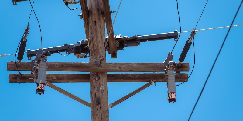
Re-fusing errors are a recognized challenge during outage restoration and are often accepted as a cost of doing business. But the scale of fuse replacement across an overhead distribution system makes their impact on coordination hard to overlook.
Medium-to-large investor-owned utilities can average about one overhead fuse cutout for every 20 to 40 customers. With most distribution faults originating on overhead laterals, utilities face frequent fuse operation and replacements. Each replacement made under restoration pressure creates an opportunity for an oversized fuse to be installed, disrupting the intended protection scheme.
These oversized fuses introduce particular coordination challenges that utilities can avoid with advances in protection technology.
The Coordination Challenge of Re-Fusing
A resilient distribution protection scheme relies on a complex architecture of independent parts executing a perfectly timed sequence. Protection engineers establish that coordination through an intentional hierarchy of device time-current characteristic (TCC) curves.
Balancing those curves is part art, part science, with one goal: ensure a fault of a given magnitude and location is cleared by the intended device within the appropriate time window.
When the system operates as designed, outages are contained, equipment is protected, and service interruptions are minimized. But when a fuse is replaced with a higher ampere rating, that balance is disrupted. It becomes a risk waiting for the next fault in that zone of protection.
What 1 Oversized Fuse Can Do
When a fuse with a higher ampere rating is installed, it may respond more slowly or fail to operate within the range intended by the original protection design.
To see how that plays out, let’s look at a typical single-phase lateral. This lateral has an L-N voltage of 7.2 kV (system voltage = 12.47 kV), and there is 4 kA of available fault current at the head of the lateral. This lateral provides power to 50 residential meters across the lateral and two sublaterals: 30 meters on the lateral itself and 10 on each sublateral.
The head of the lateral is protected by a 100K fuse, and the sublaterals are protected by 50K fuses.
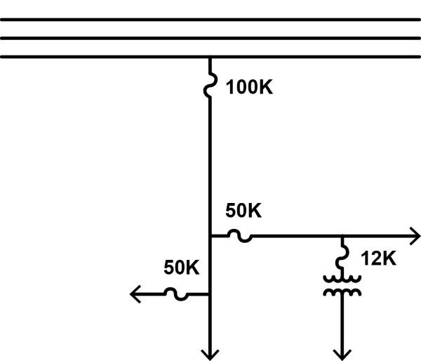
One-line diagram example of a lateral circuit.
Overtripping and Nuisance Outages
Coordination is easy to lose between two fuses in series. Consider a common storm scenario using the diagrammed lateral.
A tree branch falls onto one of the sublaterals, causing a temporary fault. The 50K fuse blows, isolating the outage to the sublateral. When conditions are safe for restoration, a crew arrives at the 50K sublateral fuse site. But they don’t have a 50K fuse link on their truck.
The crew’s prime directive is restoring power as fast as is feasible. There’s no time to go get the right fuse from the service center. Replacing it with a smaller fuse would risk a nuisance outage, so they use a 100K fuse, the next largest on the truck.
Service is restored, but now series coordination between the lateral and the sublateral has been lost. As the curves show, the fuses now overlap.1
Any fault on the 100K-protected sublateral is now also within the 100K lateral fuse’s zone of protection. The next time a fault occurs on the 100K sublateral, both the lateral fuse and the sublateral fuse will operate and take out all 50 customers on the lateral.
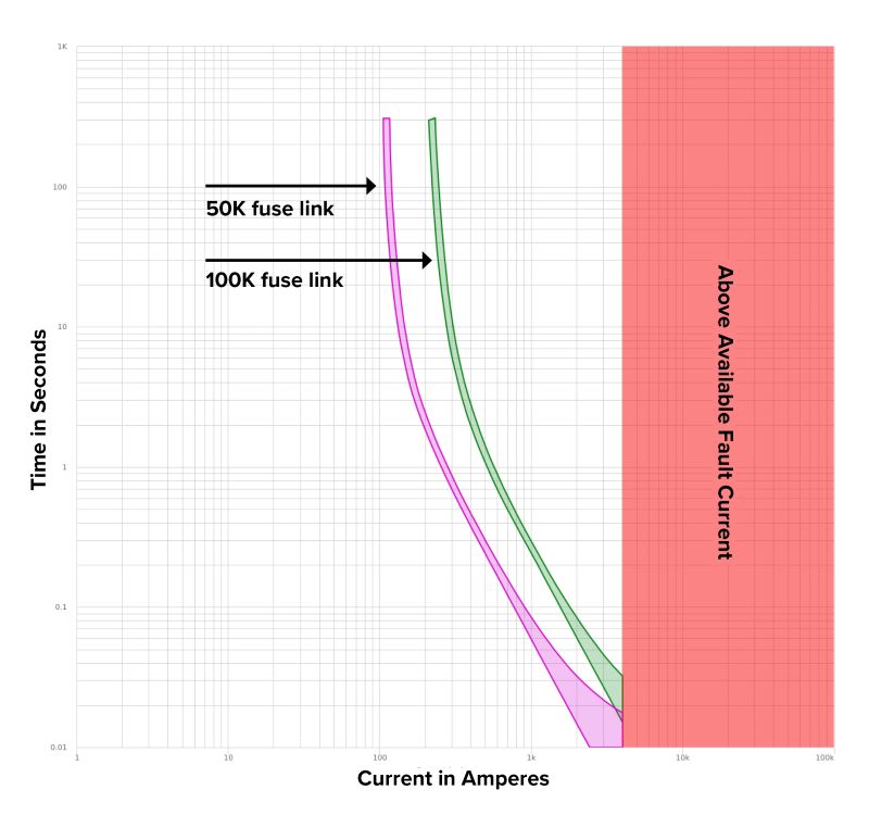
Series coordination of 100K lateral fuse and 50K sublateral fuse.
Not only does this worsen reliability, but it also results in a more expensive truck roll. With two fuses having blown, there’s more line patrolling required and more fuses to replace.
Things can escalate further if a feeder recloser is set to fuse-save the 100K lateral fuse.
With a 100K sublateral fuse installed where a 50K should be, the feeder recloser is now effectively trying to fuse-save for faults in the sublateral fuse’s zone of protection.
A temporary fault on the sublateral serving customers now results in a momentary outage for every customer on the feeder, assuming fuse-saving is successful. If not, everyone downstream of the feeder recloser experiences a blink, and every customer served by the lateral is out permanently. Plus, both the lateral and sublateral fuses now need to be replaced.
Miscoordination and Equipment Damage
An oversized fuse also puts equipment at risk. Zoom in on the 50K sublateral, and we find a 12K fuse protecting a 50 kVA single-phase transformer.
In this scenario, wildlife contacts the secondary terminals of the transformer. This creates a secondary fault of a couple hundred amps as seen by the transformer fuse2. As designed, the 12K fuse operates to clear the fault. During restoration, the crew does not have a 12K replacement available and installs the next largest amperage size, a 50K fuse, to restore service.
There is still a reliability risk in this situation. Any fault in the transformer fuse’s zone of protection will now also cause the sublateral fuse to operate. But the more damaging risk is to the distribution transformer.
The 12K fuse provides reasonable transformer protection against damage while not causing nuisance operation during magnetizing inrush or cold-load pickup. The 50K fuse, by contrast, is completely to the right of the transformer damage curve (see the plot below1), leaving the transformer unprotected.
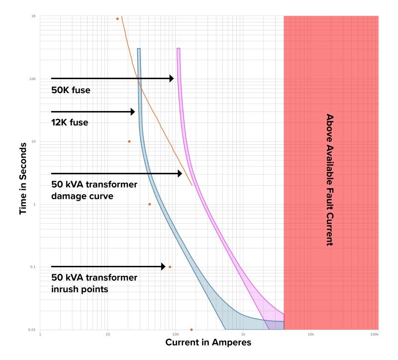
Series coordination of 50K sublateral fuse, 12K transformer fuse, and 50 kVA transformer damage curve.
The next time a fault occurs on the transformer secondary, the transformer will likely experience damage due to the fault current not being cleared in time by the oversized transformer fuse. Now restoration will require additional costs, equipment, and outage time.
Reduce Risk by Eliminating Fuse Replacement
Utilities have traditionally addressed re-fusing-based coordination changes through periodic reviews, engineering studies, and field audits. But to reduce re-fusing risks and ease pressure on crews, utilities can simply eliminate the replacement step altogether.
Advanced protective devices maintain their TCC curves permanently, eliminating the need to match fuses and maintain a large inventory. Resettable fuse alternatives go further: They can clear faults without requiring replacement.
S&C’s TripSaver® Reclosers and VacuFuse® II Self-Resetting Interrupters install into cutouts like fuses and lock out and drop open for permanent faults. But instead of introducing opportunities for error with every operation, the devices can simply be closed back into the cutout to restore power after the crew has completed any necessary downstream repair work.
If automatic reclosing is initiated, the devices will test the line and automatically restore power in the event of a temporary fault. No manual intervention is required.
The result is a more consistent protection approach:
- Crews experience less pressure to locate and verify the correct replacement fuse.
- Protection settings remain consistent across operations.
- The chance for errors is reduced to protect system coordination and reliability.
Re-fusing has long played an important role in restoring overhead distribution circuits. But as your utility manages persistent grid activity and greater expectations for rapid restoration, even small, isolated risks deserve a system-level response.
By reducing or eliminating the need for fuse replacement, you can preserve your carefully coordinated protection schemes, support crews in the field, and strengthen resilience and reliability across the distribution grid.
1 TCC curves were plotted using Coordinaide™—the S&C Protection and Coordination Assistant.
2 7A full-load current / 2.5% transformer impedance = 280A through-fault current, not accounting for impedance of the fault connection.
Looking for a smart alternative to conventional fuses?
Explore S&C’s TripSaver® Reclosers.